
F.A.Qs. For Lada Niva
There are no hard and fast answers to most of these questions. No matter what you are told by one owner another will tell you something else. If anyone disagrees with or would like to add to the answers I have here they should just write down the correct answer ( make it as short and direct as possible ) send it to me and I’ll be very happy to post it to the list.
Disclaimer
These Answers are NOT necessarily as per the workshop manual and I am NOT a licensed mechanic !
They are only intended to give you some vague idea as to how to overcome a problem or to satisfy your curiosity.
I suggest you consult a licensed mechanic or official workshop manual before carrying out any work on your vehicle.
1. I am planning on buying a Lada Niva. What should I look for.... ?
For a comprehensive check list click here
a. Normally check the same as for any vehicle.
b. The main problem areas for Niva are;
1. Rust
2. Gearbox
3. Gearbox / Transfer case alignment
4. Electrical Problems ( mainly loose fuses )
5. Cabin Heater shutoff valve.
There are other things listed in the comprehensive list but the above seem to be the most re-occuring problems mention on the group discussion lists.
2. What Kind of Fuel Consumption can I expect .........?
A. How long is a piece of string ????? This can vary so much that I’m hardly game to try to answer it ! about 10L per 100klms would be about average on the highway. Some get more, some get less. Off road ? well just take a few spare jerry cans ! It’s better to measure in litres ( or gallons ) per hour !
3. What size tyres & wheels fit the Niva......................?
Niva comes with 16" wheels, 6.95 X16 tyres, unless fitted with special 15" wheels such as the Cossack, Toro and a few others. Every owner has a different opinion on which wheels are the best ! The Suzuki, F150 Ford, and some other 15" are OK, BUT you must be aware of the offset ! Personal experience tells me that the Suzuki Vitara wheels do fit and look OK but the offset is way wide ! makes steering very heavy and could be hard on wheel bearings. Also there is the LAW to consider ! Different laws for different countries. BWA make a very good 15" wheel if you can find them. If you go to 15" tyres look around till you find a tyre that is as close to the same circumference as the original 16" so as not to upset the reading of the speedometer and the gearing. Also so they don’t rub on the wheel arches.
4. Do all Nivas vibrate...................................................?
A. NO !!!!! No Nivas should vibrate !!! However, due to poor alignment of the gearbox, transfer case and rear axle most DO give off varying degrees of vibration. This CAN be prevented or at least minimised !
5. How do I stop the vibrations ..........................................?
A. Hey ! I thought YOU could tell ME !! Here is a look at the correct alignment I'll add some methods of how to achieve it when I get time.
6. What sort of speeds can I expect from my Niva ...........?
A. Just ask each owner ! They each have the fastest Niva out there ! Officially ............. 137kph !!!!!!!
If it is worked out mathamatically a standard Niva with standard gear & tyres CANNOT go faster than 137 kph.
"My 1987 Niva with a close to dead 1.6 also managed to get up to 140+ on a good day, on a flat road. But, potholes, undulations in the road and inclines higher than 1 degree drop the speed drastically." Reece Hoffmann
" I have a 92 EFI Toro. It cruises well on 110 Km/h +, even on LPG. I've managed the top speed of 137 km/h with little effort." Roger Schulz;
Basically, you should be able to cruise comfortably at around 110kph ( 65-70 mph ) BUT, speed drops off fast with the slightest incline. These vehicles were built for OFF-ROAD work. If you want to travel fast, go look up Porsche !
7. Can I remove the Rubber Doughnut ( Intermediate Drive shaft ) without removing the transfer case................. ?
A The " Doughnut " and joint ( CV or Universal ) CAN be removed without taking off the transfer case. You need to fit a 6" hose clamp around the rubber ring before you undo the bolts ! Otherwise you can’t slip the bolts out ! Mark exactly where the T/C is positioned ( spray some paint around it's housing ) so you can get it aligned correctly when you refit it ! Simply loosen the transfer case ( T/C ) mounting bolts then undo the four bolts that attach the joint to the transfer case, slide the T/C back just a little, then undo the three large bolts that hold the " doughnut " to the gearbox. If you have the hose clamp in place and tight, the bolts should slip out easily. The whole unit should now fall out !! Ha ha !! Remember ! it is mandatory to lose the skin off at least four knuckles while carrying out this job ! Before you put the coupling back in make sure that large nut at the end of the gearbox shaft is tight ! Then all you need to do is realign the T/C so you don’t get vibrations ! Oh what fun !
8. Has anyone ever welded the spidergears together
in their Niva (for permanent off-road use only of course) to make a "it's locked all-right" diff?
A. "Yes you can weld up your rear diff and not worry about breaking the axles.....its the pinion gear that normally breaks first I quite often break front inner driveshafts on the spline in the diff this happens usually when one wheel is in the air spinning & suddenly gets contact with the ground giving the axle a big "shock" with your rear diff welded you can still drive on the road quite happily just be a bit more careful driving round sharp corners in the wet."
Simon, Auckland NZ
Warning !!! If you live in Australia and you have a crash, you can kiss your insurance goodbye if you do this !! Please let me know when you will be on the road..... so I can get OFF IT !!!!!!!
9. Which diesel Engine can I use in a Lada Niva .............. ??
A. It seems there are several different types of Diesel engine that can be fitted to a Niva with minimum fuss. Most popular in South America seems to be the VW 1600 from the MkII Golf. Toyota is also popular and Izuzu, even the old Peugeot 1905 indirect injection.
If you know of any others and the type numbers please let me know so I can list it here.
10. Can I fit a 2ltre engine to my Niva................... ?
A. Yes ! Check out this site http://homepages.paradise.net.nz/~cloggy/
He has recently fitted a Fiat engine and can show you what is involved.
11. Can I fit a Diff. Lock to my Niva .................????
I have been in DIRECT contact with Powertrax (the makers of the Lock-Right) over the past 18 Months. No other differential that they produce directly interchanges with Lada. They did agree that one COULD be produced for the Niva, but the only catch is a 100 unit minimum order would be needed to start production, and they would want 50% of the money UP FRONT before they would do it. The price would be between $250 and $300 US, depending on final production cost. Fiat 124 centre sections are a direct bolt in (I have tried this); Fiat offered a limited slip diff, if you can find one. A Locking Diff was available & manufactured in Australia, but This unit is no longer available. Try contacting the Aussies to find one.
Gavin Warren. Lada Owners Club Canada.
12. Can I fit Power Steering to my Niva............. ???
A. Much the same as for the Diff Locks. Power steer units were made in Europe but were for the left hand drive. Some-one was going to produce them for RHD but the minimum order was 1500 units ! I believe several owners have fitted a Toyota unit without too much fuss. Not sure of the model it comes from at this stage ( can some-one let me know ? )
13. Can I put my Niva on higher springs ( about 4cm.)
Would the axles break much easier ?
A." Ride hight can have a major effect on braking and steering stability. I have Monroe air shocks on the rear of my Niva ute. Used correctly when there's a fair weight on the rear they keep you from bottoming out. If you pump them up to 80-90 psi you can get about 3 - 4 inch lift. More than what I'd recommend as the shockers are pretty solid and not doing their job. A side effect of this extra height is that if you break hard the front dips and the car veers to the right. This is caused by the set up of the panhard rod in the rear axle. The ideal suspension setup is where the panhard rod is as nearly parallel to the rear axel. If you do not lengthen the support bracket on the panhard rod so that you keep this near horizontal position hard braking will cause the rear axle to lose alignment causing the Niva to veer to the right. The greater the lift the more misalignment occurs and more sudden the the veer. Having solid shockers didn't help me, but when I slammed on the brakes to avoid running into the rear of a suddenly stopped line of traffic my Niva entered a spin to the right onto the grass median strip. (The car behind me rearended the car in front of me). Other than having to go home to change my jeans I got off Scott free, but I haven't driven at speed with the shockers pumped up fully. Be careful with major suspension changes as they can build in unexpected consequences."
Paul. Melbourne
"From an engineering point of view, the only mechanical stress involved in raising the suspension will be on any universal joints as they will be working at a more acute angle than what they were designed for. This will also apply to the wishbones and any other 'moving part' that has an altered angle. The only reason (that I can see) for an increase in axle breakages is that, with the improved ground clearance, drivers are able to attempt terrain that would be otherwise inaccessible due to height restrictions......thereby putting all components of the drive train under greater stresses. My personal feelings are to leave 'lifting' the vehicle alone unless you have 'deep pockets' and 'bottomless bank balance'.Slightly improved ground clearance can be gained by looking at wheel and tyre size......for example, I have fitted 205R16 tyres to my Niva and gained (just) over 1 inch extra clearance without affecting any drive train angles."
Vern.
14. How deep can a Niva go.............??????
A. Well that depends a) on your Niva and b) on how wet you want to get.
a) "You can equip your Niva and make it go really deep (as I have done). You need a snorkel to the air intake, a valve on the exhaust or a second snorkel and really good sealing of in-hood electric's. I use gloves for that right now although I have made some plastic covers. Keep in mind that even cables need sealing. At the sparkplugs there are holes to let pressure come out. If you seal those the cables might pop out. I used a piece of tape with some silicon making something like a primitive one way valve. If you don't do all that you should know that you can get the exhaust in water as long as you have the motor running and you should never let water reach the intake. A common problem with offroaders is that the engine stops not from the depth of water but from the splash the entrance to water or a sudden stop-and-run causes. Cover the front and the hood with something waterproof, move with a steady speed creating a small (and I mean SMALL) wave in front of the car and you'll be ok. avoid turning around and manoeuvring in water. And now for the second part."
b) "How wet can you get?? Keep in mind that the Niva will never get a waterproof interior. This is good and bad. It is good because you get better traction when water comes in. But it is really bad as water can destroy anything and get you wet. There are some ways to seal various parts but water will be coming from everywhere. Anyway that doesn't limit the capability of the car but of the driver."
Jason.
"Just a few more things to add to Jason's comments. It pays to replace the breather caps on the diffs, transfer case and gearbox with hoses routed to places where the water will (or should) never reach. This is to prevent water from being sucked past the seals as the air in the warm gear housings contracts after being dunked in cold water. Before crossing deep water slacken off the fanbelt so it can slip. The reason for this is (not so important on a Niva with plastic fanblades) to prevent the fanblades from bending forward when submerged in water and contacting and possibly cutting through the radiator core. Also expect more frequent alternator and starter motor rebuilds as these units are not designed to be operated under water. Apart from that the real limit to how deep you can go is keeping the spark going to the plugs and keep water out of the airfilter.
Lada specifies a maximum fording depth of 0.5 meters on a stock standard Niva."
Pierre.
15. Can I fit a Larger Fuel Tank ............????
A. Several owners have successfully fitted larger tanks. One is from a Datsun 1600. The exhaust has to be re-routed to make up the space available and an external filler installed.
"There's a number of other Long range tanks in use in the club up to $700ish Brown Davis custom made tanks. One option I like is using a efi tank out of a Mazda 121 which has its own internal pressure pump. You hook the additional tank up to your existing one and when the main tank is empty you top it up from the rear tank by running the pump. This is a lot less complicated than getting the existing fuel pump to switch from tank to tank. You may wish to be careful on the size of the tank. Much more than 45lt that far to the rear of the Niva must have some serious balance and steering issues to be provided for."
Paul . Melbourne
Still under construction more to come !

Vaz - 21213
This section is for those who don't have a workshop manual. I will add more to it as time goes on, if you feel it is needed.
These instructions are verbatim from the workshop manual so don't argue with me ! Tell it to AutoVaz !
The art of good Trouble Shooting is to follow a process of elimination, methodically.
1. Engine
a. Engine fails to start.
Cause Remedy
1. No fuel in carburettor - fuel pipes or filter clogged. Wash fuel pipes, wash fuel tank, replace filter.
Fuel filters of carburettor and/or fuel pump clogged Wash filters
Defective fuel pump Check operation of pump & replace defective parts
2. Defective Ignition System See "Ignition System"
3. With ignition ON carburettor electromagnetic valve fails to open.
Torn off wires laid to control unit or valve Check wires and connections, replace defective wires
Defective control unit Replace control unit
4. Carburettor choke valve fails to open when engine starts firing Eliminate trouble in carburettor cold stating unit
Engine Runs Erratically or Stalls at Idle
1. Disturbed idling adjustment Adjust Idle speed
2. Defective control system of carburettor electromagnetic valve See " engine fails to start "
3. Carburettor faulty; carburettor jets or channels blocked airblast jets and channels
water in carburettor remove water from carburettor, suck out sediment from fuel tank
leaky diaphragm of cold starting unit replace diaphragm
4. Ignition System faulty see " Ignition System " chapter
5. Air leakage through damaged hose connecting intake manifold with brake vacuum booster. Replace damaged hose.
6. Air leakage in connections of intake manifold with carburettor or cylinder head Tighten up nuts or replace gaskets, eliminate deformation or caburettor flange or replace carburettor.
7. Air leakage through damaged tube along which vacuum is fed to vacuum spark timer of ignition distributor Replace damaged tube
Engine Lacks Power & Pickup
1. Carburettor throttle valve open incompletely Adjust throttle valve control linkage
2. Air cleaner clogged Replace cleaner element
3. Ignition System faulty see " ignition system " chapter
4. Fuel Pump faulty Check pump performance and replace damaged parts
5. Carburettor faulty: acceleration pump defective check pump capacity, replace faulty parts main jets clogged airblast jets choke valve opens incompletely Adjust choke valve linkage. wrong fuel level in float chamber Adjust float level setting defective diaphragm of power duty economizer replace diaphragm
6. Choked vent tube of fuel tank Blow through the tube with compressed air
7. Wrong valve clearances Adjust clearances
8. Timing phase marks out of alignment Change position of chain to align marks
9. Compression below 1MPa ( 10kgf/cm2 ) : broken or sticking piston rings Clean rings and piston grooves from carbon, replace damaged parts poor seating of valves grind seats badly worn cylinders and piston rings replace pistons, rebore and hone cylinders
Crankshaft Main Bearing Knock
As a rule this knocking, of a dull metallic nature, is detected when the throttle valve is sharply opened at idle speed. Its frequency grows with an increase in crankshaft speed. Excessive crankshaft end play causes a sharper sound with uneven intervals most conspicuous during gradual throttle up and down.
1. Early ignition Adjust ignition timing
2. oil pressure too low see " oil pressure too low at idle speed "
3. Loosening of flywheel bolts Tighten up to specified torque
4. Excessive clearance between thrust halfrings and crankshaft Replace thrust halfrings by new, thicker ones
5. Excessive clearance between main journals and their bearing shells. Grind journals and replace shells
Big-End Bearing Knock
Usually knocking of big-end bearings is sharper than that of the main bearings. It is heard at engine idling speed when the throttle valve is sharply opened. The origin of knocking can be easily identified by disconnecting spark plugs one after the other.
1. Insufficient Oil pressure see " Oil pressure too low at idling speed "
2. Excessive clearance between big-end journals and shells Grind journals and replace shells.
Piston Slap
As a rule it is a dull knocking caused by slackness of piston in the cylinder. It is best audible at a low engine speed and under a load.
1. Excessive piston-to-cylinder clearance Replace pistons, rebore and hone cylinders
2. Excessive piston ring-to-groove clearance Replace rings or pistons with rings
Intake and Exhaust Valve Knock
Excessive clearances in valve gear cause characteristic knock, usually with regular intervals. Knocking frequency is less than that of any other engine knock, since the valves are operated by the camshaft which rotates at half the crankshaft speed.
1. Excessive valve-to-rocker clearance Adjust clearance
2. Valve spring broken Replace spring
3. Excessive clearance between valve stem and guide Replace worn parts
4. Wear of camshaft cams Replace camshaft and valve rockers
5. Loosening of adjustment bolt locknut Adjust valve rocker-to-cam clearance and tighten locknut
Camshaft Drive Chain Noise
The camshaft drive chain noise becomes noticeable against the background of general engine noise in case of excessive clearance between the chain and sprockets and it is particularly loud at low engine speed.
1. Chain becomes slack because of wear Tighten up chain
2. Chain tensioner shoe or damper broken Replace tensioner shoe or damper
3. Chain tensioner plunger rod jamming Eliminate jamming
Oil Pressure too Low in Warm Engine at Idling Speed
1. Foreign matter getting under reducing valve of oil pump Clean valve of foreign matter and burrs, wash oil pump
2. Oil pump gears worn Repair Oil pump
3. Excessive clearance between crankshaft main journals and bearing shells Grind journals and replace shells
4. Excessive clearance between camshaft journals and bearing housing Replace camshaft or bearing housing
5. Use of engine oil of poor quality or no-recommended grade. Replace oil with that recommended
Oil Pressure too High in Warm Engine
1. Oil pressure reducing valve jamming Replace valve
2. Excessive rigidity of oil pressure reducing valve spring Replace spring
Excessive Oil Consumption
1. Oil leakage through engine seals Tighten fastenings or replace gaskets and glands
2. Choked-up crankcase breathing system Wash parts of crankcase breathing system
3. Wear of piston rings or cylinders Rebore cylinders and replace pistons and rings
4. Broken piston rings Replace rings
5. Gummed slots in oil control rings or cut-outs in piston grooves caused by use of oil of non-recommended grade Remove carbon from slots and cut-outs, use recommended oil
6. Valve oil-deflecting caps worn or damaged Replace caps
7. Heavy wear of valve stems or guides Replace valves, repair cylinder head.
Excessive Fuel Consumption
1. Choke valve fails to open completely Adjust choke valve linkage
2. High resistance to car motion Check and adjust tyre pressure, brake system, front wheel alignment
3. Wrong ignition timing Adjust ignition timing
4. Ignition Distributor vacuum spark timer faulty Replace vacuum timer or ignition distributor
5. Carburettor fuel level too high; carburettor needle valve or its gasket leaky look for foreign particles between valve seat and needle replace gasket or valve, if necessary. jamming or friction interfering with normal motion of floats Examine floats and replace them if necessary.
6. Carburettor air jets clogged. Clean jets.
7. Disturbed tightness of diaphragm of carburettor power duty economizer Replace diaphragm
8. Weak spring of power duty economiser Replace spring
9. Carburettor electromagnetic valve fails to cut off fuel delivery at forced Clean contact surfaces of switch idling; movable contact of limit switch in carburettor fails to connect to ground ; open circuit fault in wire connecting control unit with carburettor limit switch Check wire and it's connections, replace damaged wire. Defective control unit Replace control unit.
Engine Overheats
Pointer of coolant temperature gauge is in red zone of scale. Prior to trouble shooting check coolant temperature gauge and its transmitter for good repair.
1. Slackening of pump and alternator drive belt Adjust belt tension
2. Lack of coolant in cooling system Add coolant into cooling system
3. Wrong ignition timing Adjust ignition timing
4. Radiator heavily soiled on outside Clean radiator with jet of water
5. Thermostat faulty Replace thermostat
6. Defective valve in radiator cap ( opening pressure below 0.07MPa ( 0.7kgf/cm2 )) Replace cap
7. Coolant pump faulty Check , replace or repair coolant pump
Rapid Drop of Coolant Level in Expansion Tank
1. Radiator damaged Replace or repair radiator
2. Damaged hoses or pipe joint gaskets, loose clamps Replace damaged hoses or gaskets, tighten up clamps
3. Coolant leaking from heater cock or heater radiator Replace cock or heater radiator
4. Coolant leaks through coolant pump gland Replace gland
5. Radiator cap or its gasket damaged Replace cap
6. Cylinder head gasket damaged Replace gasket
7. Leakage of coolant through microcracks in cylinder block or head Check cylinder block and head for leakage of coolant, if cracks are detected replace defective parts
8. Leakage of coolant through microcracks in coolant pump body, cooling jacket outlet connection, expansion tank or intake manifold. Check for coolant leakage, if cracks are detected, replace damaged parts, minor leaks may be eliminated by type HNNC-1 stopleak into coolant
Clutch Drags
Cause Remedy
1. Excessive clearance in clutch control mechanism Adjust Clutch control mechanism
2. Warpage of driven disc ( face runout over 0.5mm ) Straighten or replace disc
3. Roughness of driven disc facings Replace facings or driven disc assembly
4. Loosening of rivets or breaking of driven disc facings Replace facings, check end runout of disc
5. Jamming or driven disc hub on gearbox clutch shaft splines Clean splines and coat them with grease. If jamming is caused by mutilation or wear of splines replace clutch shaft or driven disc.
6. Breaking of plates connecting thrust flange with clutch cover. Replace clutch cover complete with pressure plate
7. Air in hydraulic system Bleed hydraulic system
8. Fluid leaks from joints or damaged pipes of hydraulic system Tighten joints, replace damaged parts, bleed hydraulic system
9. Fluid leaks from master or operating cylinder Replace sealing rings, bleed system
10. Clogging of hole in reservoir cover which causes depression in master Clean up hole in reservoir cover, bleed system cylinder and infiltration or air into cylinder through seals
11. Poor tightness caused by soiling or wear of master cylinder front sealing ring Clean sealing ring or replace if worn
12. Warpage or skewness of pressure plate Replace clutch cover complete with pressure plate
Clutch Slips
1. No clearance in clutch control mechanism Adjust clutch control mechanism
2. Heavy wear or burning of driven disc facings Replace friction facings or driven disc assembly
3. Oiling of driven disc facings, flywheel and pressure plate surfaces Wash oiled surfaces, eliminate cause of oiling
4. Clogging of master cylinder compensating hole Wash cylinder, clean up compensating hole
5. Clutch control mechanism damaged or jammed Eliminate faults that cause jamming.
Jerky Engagement of Clutch.
1. Driven disc hub seized on clutch shaft splines. Clean splines, lubricate them with grease. If seizure is caused by mutilation or wear of splines, replace clutch shaft or driven disc.
2. Oiling of driven disc facings, flywheel and pressure plate surfaces Wash oiled surfaces carefully with white spirit and eliminate cause of oiling.
3. Jamming in clutch control mechanism Replace distorted parts. Eliminate cause of jamming.
4. Heavy wear of driven disc friction facings Replace facing with new ones, check condition of disc surface.
5. Loosening of driven disc facing rivets Replace faulty rivets and if necessary, facings
6. Pressure plate warped or it's surfaces damaged Replace clutch cover complete with pressure plate.
Noisy Clutch Disengagement
1. Breaking or loss of resilience of driven disc damper springs. Replace driven disc assembly
2. Clutch release yoke return spring broken, lost it's resilience Fasten spring as required or replace by new one
3. Breaking of plates connecting pressure plate with cover Replace clutch cover complete with pressure plate.
Vibration of Transfer Case and Body Floor ( in front seat area ) at Starting from Rest and Acceleration to 80 km/h
Cause Remedy
1. Misalignment of transfer case relative to engine unit. Align Transfer case
2. Loose or damaged supports of transfer case or rear supports of engine unit. Tighten attachment nuts and bolts or replace supports.
3. Stiff turning or binding in one of planes of front or rear propeller shaft joints. Repair universal joints or replace shafts assembly.
4. Incomplete release of parking brake. Adjust parking brake.
5. Stiff turning of constant velocity universal joint of intermediate Check condition of boot and joint. If joint parts are damaged, replace joint propeller shaft.
Vibration of Transfer Case and Body Floor ( in front seat area ) in Motion. ( especially at 80 - 90km/h )
1. Propeller shafts out of balance Replace or repair propeller shaft.
2. Centre differential out of balance Replace or repair centre differential
3. Binding in universal joints of front or rear propeller shafts Repair universal joints or replace propeller shafts in assembly
4. Binding of constant velocity universal joint of intermediate propeller shaft Check condition of boot and joint. If parts are damaged, replace them
5. Loose bolts and nuts of engine mounts or defective engine mounts Tighten up bolts and nuts or replace engine mounts
6. Bending of bolts and flexible coupling flange of intermediate shaft Replace bolts or intermediate shaft
Noise on Turns or During Slipping of Wheels
1. Difficult rotation of differential pinions on shaft Replace damaged or worn parts
2. Jamming of axle drive gears in differential housing Replace worn or damaged parts
3. Damaged working surface of pinions Replace worn or damaged parts.
4. Excessive end play of axle drive gears in differential housing Set a clearance of 0 - 0.10 mm with adjusting shims.
Difficult Gearshifting or Differential Locking
1. Sleeve jammed on splines of hub or differential housing. Dress off any burrs, nicks or scores, replace defective parts
2. Nicks on teeth of smaller rim of high or low speed gears, also on teeth Dress off any nicks or burrs, replace faulty parts of sleeves and on splines of front axle drive shaft
3. Bent fork or shift bar Straighten distorted parts
4. Distortion of transfer case control levers Straighten levers or replace them by new ones, if necessary
5. Jamming of control levers on axles Remove levers, clean axles and bushings. replace faulty parts
Uncontrollable Disengagement of Gears or Differential Lock.
1. Wear of gear and sleeve teeth. Replace worn parts
2. Detent springs lost their resilience or it's parts heavily worn Replace springs or worn parts
3. Incomplete engagement of gears and differential lock caused by distortion Straighten or replace distorted parts, dress down nicks and burrs, replace defective parts of control parts or nicks on gears, sleeves and splines.
Leakage of Oil
1. Sealing gaskets damaged Replace gaskets
2. Loosening of cover-to-housing nuts and studs Tighten up nuts and studs at places of leakage
3. Shaft glands worn or damaged Replace glands
4. Worn sealing rings of transfer case shift bars Replace sealing rings
Method of Detecting Causes of Vibration of Transfer Case and Body Floor ( in front seat area )
First of all note the speed at which the vibration of the transfer case appears and then proceed to detect it's cause.
Test No. 1
Set the transfer case and gearbox levers in neutral and start the engine. Raise the crankshaft speed to the value corresponding to the car speed at which the vibration appears ( ie. same number of revs on Tachometer )
If Vibration appears on the motionless car, check attachment and condition of the engine mounts as they cause the vibration.
Test No. 2
If test No. 1 does not reveal vibration, set the transfer case levers in neutral, start the engine, shift into direct drive in the gearbox and set the crankshaft speed corresponding to the car speed at which the vibration of the transfer case appears.
If vibration is detected on the motionless car, it's cause is a defect in the intermediate propeller shaft. ( unbalance, bending of the bolts or flange of the flexible coupling, jamming in the constant-velocity universal joint ).
Test No. 3
If tests No. 1 & 2 do not reveal vibration, proceed with test No. 3. For this purpose, race the car to the speed at which vibration is detected and set the transfer case and gearbox levers in neutral. If vibration persists, the cause of trouble is a defect in the front or rear propeller shafts ( unbalance, jamming of the universal joints ) or unbalance of the centre differential.
To Install and Align the Transfer Case
Make sure that the engine mount pads are properly installed in the brackets ( the centring washers of the front mount pads of the engine should get into the respective holes in the side brackets ) and the transfer case mounts tightly fit the body bottom. If necessary, straighten the surface of the body under the mounts.
Mount the transfer case in the car without tightening completely the the transfer case mount bracket nuts 4 & 5 .
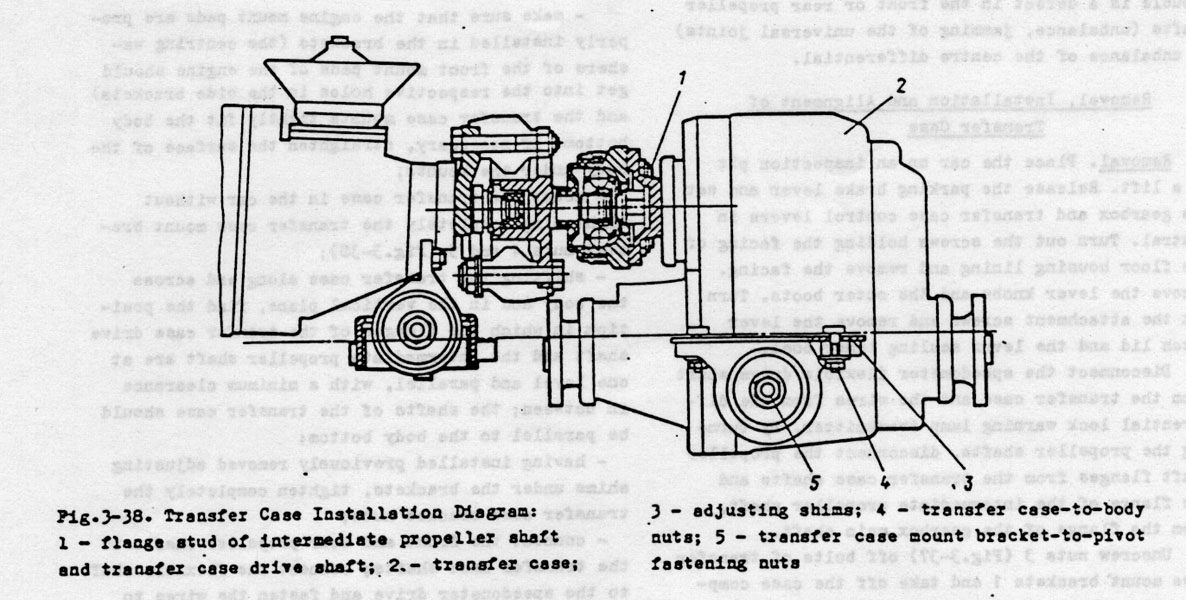
Shifting the transfer case along and across the body and in the vertical plane, find the position in which the flanges of the transfer case driveshaft and the intermediate propeller shaft at one level and parallel, with a minimum clearance in between; the shafts of the transfer case should be parallel to the body bottom;
Having installed previously removed adjusting shims under the brackets, tighten completely the transfer case bracket nuts.
Connect the front and rear propeller shafts to the transfer case shafts; connect the flexible shaft to the speedometer drive and fasten the wires to the transmitter of the differential lock warning light.
When replacing the transfer case and also in case of sagging of the engine rear mount which causes vibration of the transfer case, select adjusting shims of a required thickness and install them in place. To select the shims proceed as follows; Make sure the engine mount pads are installed correctly in the brackets; separate the flanges of the transfer case drive shaft and the intermediate propeller shaft; loosen the nuts holding the transfer case mounts to the body, remove adjusting shims and, shifting the transfer case along and across the body in the vertical plane, fine the position of the transfer case in which the disconnected flanges are at one level and in parallel with each other and the clearance between the flanges is minimum and the transfer case shafts are parallel to the car bottom; fill up the clearance between the body floor and the supports with the required number of shims; align the centring bolts of the flanges, taking care to prevent interference in the transfer case and engine mounts and holding the transfer case in this position, tighten up the previously backed off nuts of the transfer case mounts;
Insert and tighten the bolts of the transfer case and intermediate shaft flanges; if the bolts freely pass into the flange holes, the alignment is correct; otherwise, repeat the flange alignment operation.
Coming soon !!!!!
Fuel Injection System for 21214
Unfortunately the conversion from Russian to English leaves a lot to be desired.
However you can still get the guts of it.
Three vanish "?" (I so name it) - ??????, Having warmed up, the Failure.
Absence of these "?" practically is not noticed, but when it is possible to pass by the usual (carburettor) machine at once you understand in the winter. Sensation such, as though it to explain, well as though the board from the TV has lost...
????????? practically to zero of a problem with start-up - it is well got(started) in any weather (besides in the winter it very actually in our country)
There are no details which move, clog, and in which water (including ???????? is actually enough off-road) etc gets. Besides two ignition coils, reliable and simple system of injection (GM or Bosch, and some abuse "January"!), plus system of a self-diagnosis.
Work of the motor on bottoms softer.
But not unimportant - appreciablly big opportunity of protection against stealing (additional points of a blockage)
1. ?????????? the lead-free fuel is
necessary for the machine ("January" the Soviet variant of "brains"
just and learned(taught) there is a leaded fuel. But as shows experience a leaded fuel
harmful not only ?????? oxygen, and
business not only and not is so much in ???????????????
gasoline, how many in his(its) quality.
Even in the big cities where problems with gasoline be careful less.
2. Higher qualification of those who serves (?.?. The owner)
I try it to correct publishing the information on injection. But
time will take the - you see of switchboards on "eights" too at first were
afraid...
3. Higher cost of specific spare parts and their smaller prevalence.
Pleases, that they on the order it is more reliable, and due to
system of a self-diagnosis failure first at once is found out, second the automobile(car)
can ??????????? only the gauge of position of a bent shaft...
4. Less interesting (all works also)
Yes the Field is an automobile(a car) of PRESENT ?????, but it is
possible to step in the qualification ABOVE...
On ?????????? to the machine to go better - believe me...
On the automobile(car) the VAZ - 21214 is established the engine of model the VAZ - 21214 with the central injection of fuel.
Basis of the device of system with the central injection of fuel is the electronic control package (???; In technical literature ??? frequently call the controller) with ????????????? the head (hydraulic unit). ??? represents the microcomputer with rigidly given program on steering of work of the engine on all modes of operation. Problem(task) ??? includes continuous processing of the acting information while in service from gauges on the given algorithm of steering and distribution of managing signals (commands((teams)) on executive elements of an engine management for maintenance of optimum parameters of movement of the automobile(car) (a fuel consumption, power, toxicity ??) depending on service conditions.
????????????? the head (hydraulic unit) replaces the carburetor and represents electromagnetic ????????????? the valve with a pressure regulator of fuel. Distribution of a working blend on separate cylinders
It is carried out on a warmed intake manifold, as well as at setting the carburetor.
On ??? acts and the following
information is processed:
- About position of a throttle valve, 9 (loading);
- About a rotary speed of a bent shaft of the engine, 14;
- About temperature of acting air, 6;
- About a temperature mode of the engine, 13;
- About the maintenance(contents) of oxygen in ??, 12;
- About a pressure(voltage) in an onboard network of the automobile(car), 15.
Fuel from a tank 1, due to the electric pump 2, through a fuel filter 3 moves to central ?????????????? to the block which consists of the case of a throttle valve and hydraulic unit. The hydraulic unit consists from electromagnetic ?????????????? the valve 5 and a pressure regulator of fuel 4 which supports constant pressure in a point of a supply of fuel to a spray jet ?????????????? the valve irrespective of amount of injected fuel.
The gauges established on the engine, remove from it all basic operational parameters about their drives in ???. The system of ignition forms a signal about the valid rotary speed of a bent shaft of the engine.
The operating mode (??????????) is set to the engine by means of opening a throttle valve with use of a pedal of gas. At present time the required quantity(amount) of air is determined by position of a throttle valve which is fixed by the gauge of position of a throttle valve and a rotary speed of the shaft of the engine.
Extreme positions of the gauge of position of a throttle valve correspond to a no-load conditions or an overall load. Their definition is of great importance for enrichment at an overall load or for switching-off of a pull-rod. The signal of position of a throttle valve estimates required power and ??? determines a supply of necessary amount of fuel.
Fig. 1. The circuit of system of the central injection
??????:1-fuel tank;
2-electric fuel pump;
3 - a fuel filter;
4 - a pressure regulator of fuel;
5-????????????? the valve;
6-temperature detector of air;
7-electronic control package (???);
8 - the executive gear of a throttle valve;
9-potentiometer of a throttle valve;
10-valve of a blowdown of an adsorber;
11 - an adsorber;
12 - the L-gauge;
13 - a temperature detector ???.
Liquids;
14 - the allocator of ignition;
15 - the accumulator battery;
16 - an ignition lock;
17-relay block;
18-heating of an intake manifold;
19 - an air filter;
20 - receipt of external air;
21 - an intake manifold of a working blend
The temperature of the engine renders essential influence on required quantity(amount) of fuel. The temperature gauge is built - in system of circulation ???. The liquid are given out also with a signal in ???.
Time of a presence in an open condition electromagnetic ?????????????? the valve depends on a battery voltage. To compensate delay of operation of the valve, ??? takes into account fluctuations of a pressure(voltage) of a network by means of change of time of injection of fuel.
??? processes entrance signals and time of injection of fuel expects on their basis. ??? contains the microcomputer with the block of programs and memories, and also the analogovo-discrete converter. For ??? a critical parameters for calculation of time of injection are the signal of a corner of position of a throttle valve and a signal of a rotary speed. On their basis the program of steering which totals 225 and more reference points for maintenance of completeness of combustion of a working blend at her(it) ????????????????? structure (1:14,7) is constructed. For calculation of time of injection of fuel in intervals between reference points the additional adaptable characteristic field with 64 reference points that allows to compensate specific features of the engine and his(its) systems while in service is entered.
For achievement of formation(education) of a homogeneous blend and its(her) identical distribution (filling) on separate cylinders ????????????? the valve is located in a stream of acting air up to a throttle valve.
Radial inclined bores of a spray jet create a picture of dispersion on a taper. Dispersion is carried out by means of overlapping reflective dispersion and dispersion due to turbulences. The corner of dispersion of the valve is executed so, that fuel gets directly in a crescent spacing between the case and a throttle valve.
 Fig. 2.
Hydraulic unit
Fig. 2.
Hydraulic unit
1 - a pressure regulator of fuel;
2 - a temperature detector of air;
3 - electromagnetic ????????????? the
valve;
4 - the case of a throttle valve;
5-throttle valve;
6 - the case of hydraulic unit
For the compensation of pauperization of a working blend connected to cold walls of an intake manifold, and for simplification of start-up of cold engine EBU increases quantity(amount) of submitted fuel by increase of time of injection.
Enrichment of a blend in ????????? a condition provides smoothness of a set of power and optimum power setting at minimal, a fuel consumption.
The heat controller located in the central block of injection (the executive gear), provides additional opening a throttle valve that provides ???????? to the engine of additional amount of air that results in increase of a fuel consumption and an establishment of a required rotary speed on a no-load conditions.
It occurs due to that the potentiometer of a throttle valve fixes this changed position and thus the constancy of structure of a working blend and toxicity ?? idling are kept.
In a range of partial loadings the system brings a toplivno-air (working) blend into accord when minimal issue ?? is provided.
??? receives the information on an overall load from ???????????????????? the gauge of position of a throttle valve. The size of required enrichment of a working blend at an overall load is incorporated in program ??? by duration of injection in view of power setting.
For achievement of favorable transitive characteristics during speedup enrichment of a blend should be carried out. From change of position (a degree of conveyance) ???????????????????? the gauge of position of throttle valve ??? receives the information on speedup and his(its) degree. The size of enrichment depends on temperature of the engine and speed of conveyance of a throttle valve.
By means of a stopping delivery of fuel at an inertial motion essentially it is possible to reduce a fuel consumption and issue of toxic components ?? at movement on crossed and especially mountain, districts.
The supply of fuel stops on a signal with ??? at achievement of as much as possible allowable rotary speed incorporated in the program.
deviation(rejection) of a rotary speed of an idle running from given, at instant temperature of the engine. This system does not demand a leaving(care) and provides indemnification of change of parameters of the engine at operation.
?????? (L) - the gauge 12 established in stream ??, gives out a signal in ??? at an instant deviation(rejection) of structure of a working blend from an optimum parity(ratio) air - fuel. The system of regulation influences for the period of an open condition ?????????????? the valve.
Thus, the quantity(amount) of fuel that provides on all operating modes a parity(ratio) air - fuel only with the minimal deviation(rejection) from optimum is precisely dosed out.
Fuel from a fuel tank 27 (fig. 3) with the electrogasoline pump 26 moves under pressure on forcing highway 25 in a fuel filter 1 and further in the unit 11 central injections of fuel. The pressure regulator 3 supports a constant a pressure fall on an injection nozzle 9, and surplus of fuel on allocating(removing) highway 24 comes back in a fuel tank 27. The spray jet 9 on a command(team) of electronic control package (???) 29 opens and injects fuel in ????????????? space of the unit 11. ??? 29 forms duration of a pulse of a spray jet depending on power setting and his(its) loadings so that constantly to provide optimum structure of a toplivno-air blend.
Air in the unit 11????????? from an air filter 13. A throttle valve of the unit 11????????? a pedal of an accelerator through sector 10. The controller 29 constantly supervises position of a throttle valve and speed of its(her) movement (speedup, slowdown) through the gauge 14 established on the end of the shaft of a throttle valve. Besides ??? 29 steers an adjuster 8 idle runnings irrespective of position of a throttle valve.
At start-up of the engine when the rotary speed of a bent shaft below minimal, ??? 29 increases duration of pulses of a spray jet 9 for enrichment of a toplivno-air blend, and at start-up of the cold engine in addition through the relay 12 for the certain period includes the electropreheater in an inlet tube 2. To press a pedal of an accelerator during start-up of the engine it is inadmissible. After start-up of the engine duration of pulses of a spray jet 9 is corrected according to the given program depending on the data of the gauge of 4 air temperatures established in the case of an air filter 13, the gauge of 7 temperatures of a cooling fluid and from the gauge 17 absolute pressure which selects managing underpressure on a tube 18 of ?????????????? spaces of the unit 11. The ambassador ???????? the engine the minimal rotary speed of a bent shaft on a no-load conditions is established by an adjuster 8 idle runnings on command(team) ??? 29 depending on loading on the engine (the air conditioner, a heater is included, warmed a rear screen etc.). ??? 29 it is disconnected from steering of an adjuster 8 idle runnings at achievement by the automobile(car) of the certain speed, the information about which acts in the controller from the gauge 22????????.
Fig. 3. A feed system of the engine:
1 - a fuel filter;
2 - an inlet tube with the electropreheater;
3 - a pressure regulator;
4 - a temperature detector of air;
5 - the engine;
6 - an exhaust branch of system of cooling;
7 - a temperature detector of a cooling fluid;
8 - an adjuster of an idle running with the step-by-step engine;
9 spray jet;
10 - sector resulting a throttle valve;
11 - the unit of the central injection of fuel;
12 - the relay of the electropreheater of an inlet tube;
13 - an air filter;
14 - the gauge of position of a throttle valve;
15 - the gauge of concentration of oxygen (L-gauge);
16 - an exhaust manifold;
17 - the gauge of absolute pressure;
18 - a tube of takeoff of underpressure;
19 - a reception tube;
20 - a gear box;
21 - a catalyst converter;
22 - a speed sensor;
23 - a transfer box;
24 - allocating(removing) highway;
25 - forcing highway;
26 - the electrogasoline pump with the gauge of a level of fuel;
27 - a fuel tank;
28 - the relay of the electrogasoline pump;
29 -
At movement of the automobile(car) on
????????? engine EBU 29 forms duration of pulses of a spray jet 9 depending on the data of the gauge of 15 concentration of oxygen (feedback) established in an exhaust manifold 16.On a mode of speedup
??? 29 receives a signal ????????? 14 about sharp change of position of a throttle valve and increases a fuel delivery, and on a mode of slowdown (a mode of an engine braking) reduces a fuel delivery down to the full termination(discontinuance) of his(its) submission by the certain period. Besides ??? stops completely a fuel delivery at achievement by the engine of as much as possible allowable rotary speed of a bent shaft in avoidance ?????????? the engine, and also at achievement by the automobile(car) of the maximal speed.At occurrence of a system malfunction of a feed(meal) in an instrument cluster the indicating lamp " CHECK ENGINE " 30 lights up. Fire of a lamp does not mean, that the engine should be immediately stopped, as
??? has the reserve systems allowing the engine to work almost in a normal mode. Nevertheless, the reason of fire of an indicating lamp should be established at the enterprise of maintenance operation as soon as possible.
System of ignition - electronic. It(she) includes the module of ignition 8 (rice 3), the inductive gauge 9, spark plugs 1, high-voltage wires 2 and
??? 21. The module of ignition 8 includes two ignition coils and the switchboard, incorporated in one block. The inductive gauge 9 reads out the data from a specifying disk of a sheave 10 and generates a signal on the module of ignition 8 which develops the basic pulse sent in ??? 21. ??? uses this signal for calculation of position of a bent shaft, frequency of his(its) rotation, a firing point and width of a pulse on a spray jet. Besides ??? constantly corrects a firing point depending on the data, ??????????? on him(it) from temperature detectors of air, absolute pressure and temperatures of a cooling fluid.At start-up of the engine when the rotary speed of a bent shaft less than 400 rev/min, steers a firing point the module of ignition 8, and after start-up of the engine this function carries out
??? 21. The module of ignition 8 on command(team) ??? 21 gives out a high-voltage pulse on the appropriate spark plugs. In this system of ignition the method of " the fulfilled spark " when the spark simultaneously moves on two spark plugs of those cylinders which buckets at present are in opposite phases on timing periods is applied. So, for example, if the bucket of the first cylinder is in ??? at the end of a timing period of squeeze the bucket of the fourth cylinder is in ??? at the end of a timing period of release. On a spark in a spark plug of the fourth cylinder very insignificant power is used, and the basic power goes on a spark plug of the first cylinder.Electronic system of ignition - system of high power. Therefore at working engine the contact to elements of system is inadmissible, and also removal of plugs from the accumulator battery is inadmissible. All works in a motor chamber with elements of system of ignition should be carried out(spent) at the switched off ignition and cooled down engine.
??? 21 which is placed in interior on ???????? with legs of the driver, should be constantly pure(clean) and dry. His(its) autocratic removal and disassembly is completely inadmissible.
Fig. 4. System of ignition and a safety system of an environment:
1 - a spark plug;
2 - a high-voltage wire;
3 - a tube of fanning of a crankcase on operating modes of work of the engine; 4, 5 -
steam tubes;
6 - a breather of system of fanning of a crankcase;
7 - an adsorber with the electromagnetic valve of a blowdown;
8 - the module of ignition;
9 - the inductive gauge;
10 - a crankshaft pulley with a specifying disk of system of ignition;
11 - a tube of fanning of a crankcase on a no-load conditions of the engine;
12 engine; 13 -
At work of the engine on a no-load conditions with the minimal rotary speed of a bent shaft when the throttle valve is closed, a crankcase fumes on a tube 11 act in
????????????? space of the unit 15???????????? injection of fuel. On operating modes of work of the engine the throttle valve is open, and a crankcase fumes on a tube 3 are sucked away in an air filter 16. In a tube 3 it is established ????????????? 13, preventing penetration of a flame into a crankcase of the engine in case of failure in his(its) work.Into the given system enter a catalyst converter 20 and the gauge of 17 concentration of oxygen (L-gauge) with
?????????????????, that allows the gauge to reach(achieve) a working temperature faster. The gauge 17 gives out signal ??? 21 about the maintenance(contents) of oxygen in fulfilled gases (??) which in turn corrects structure of a toplivno-air blend up to optimum structure.The catalyst converter 20 represents the ceramic block made in a metal housing. The ceramic block has set of microports, on which surface
??????? the catalytic structure consisting of platinum, a palladium and ?????.??
which structure includes such most toxic components as a monoxide carbon (WITH), hydrocarbons (??) and oxides of nitrogen (NOx), contact to catalytic structure and as a result reactions the significant part of toxic components turns to such components, as water (H2?), carbonic gas (??2) and nitrogen (N2).The given system works regularly in the event that the lead-free fuel is used only. The leaded fuel in short term puts this system out of action as lead clogs microports of the ceramic block, covers a contact area of the L-gauge 17 which starts to give out the incorrect information on surplus of oxygen in
??, and ??? 21 in turn increases width of a pulse of a spray jet. ????????????? can leave out of operation and in case of misses(passings) in system of ignition as in this case pure(clean) fuel will act in ????????????? and the temperature in it(him) sharply will increase, that will cause occurrence of cracks(fractions) in the ceramic block. Therefore constantly it is necessary to watch(keep up) serviceable work of system of ignition and to not suppose faults in its(her) work.At the idle engine of pair gasoline from a fuel tank 31 on tubes 29 and 30 act in a separator 28 where are in part condensed also a condensate back comes back in a fuel tank. In process of accumulation
????? gasoline they on a tube 27 act in the gravitational valve 26, and from him(it) on a tube 25 in a two-way valve 24 where at the certain pressure open an outlet valve. Further on a tube 4 they act in an adsorber 7 where are absorbed ??????????? (the activated coal).After start-up of engine EBU 21 includes in an adsorber 7 electromagnetic valve of a blowdown therefore external air
????????????? through ?????????, is sated with pairs gasoline and on a tube 5 acts in ????????????? space of the unit 15 central injections of fuel. In process of the charge of gasoline in a fuel tank 31 underpressure, and external air through an adsorber 7 is created acts on a tube 4 in a two-way valve 24 where opens a back-pressure valve. Further air on a tube 25, the gravitational valve 26, a tube 27, a separator 28 and on tubes 28 and 30 acts in a fuel tank 31. The gravitational valve 26 prevents escape of gasoline from a fuel tank in system at overturning the automobile(car) in case of road and transport incident.
On rice 5 the fragment of the basic circuit of an electrical equipment of the automobile(car) the VAZ - 21214 is given. Other positions are similar to positions of the basic circuit of an electrical equipment of the automobile(car) the VAZ - 2121 (21213). The potentiometer 99 established on the top booster ????? ???????, corrects a firing point only at the enterprise of maintenance operation.
Fig. 5. The basic circuit of an electrical equipment (fragment):
90 - the main relay;
91 - the relay of the electropreheater of an inlet tube;
92 - the electropreheater of an inlet tube;
93 - the inductive gauge; 94 - the module of ignition;
95 - the gauge of concentration of oxygen;
96 - a speed sensor;
97 -
Automobiles(cars) with injection for Europe and Russia among themselves differ
structurally a little.
In systems of injection of the automobiles(cars) intended for Europe, usually there is a
feedback. The feedback assumes presence of a lambda probe (the gauge of concentration of
oxygen) in a reception tube of an exhaust system and a catalyst converter of fulfilled
gases. The computer which oders about system, under indications of a lambda probe
defines(determines) structure of fulfilled gases and corrects a fuel delivery in cylinders
that the ambassador
Preliminary treatment of an engine management system with electronic injection of fuel is simple enough
Electronic control package (
???) carries out a constant self-diagnosis. At detection of failure by him(it), its(her) code will be worn out in memory and the indicating lamp " CHECK ENGINE " on the panel of devices is included.At inclusion of ignition and the idle engine the indicating lamp should lights up, that testifies to serviceability of a bulb and system of a self-diagnosis.
After a starting engine operation the lamp is switched off.
If the lamp continues to burn, it means, that the system of a self-diagnosis has found out failure. If failure withdraws, in most cases in 10 seconds the lamp is switched off, but the diagnostic code is kept in memory
???.At initialization of a mode of a conclusion of codes of a self-diagnosis by a lamp " CHECK ENGINE " it is displayed
??????????? ??? two-digit error codes (failures) from 12 up to 99.For initialization of a mode of distribution of codes of preliminary treatment it is necessary to close at the switched off ignition among themselves contact pieces
"?" and "?" a diagnostic socket or contact piece "?" on the case of the automobile(car) and to include ignition not starting the engine.The pad of preliminary treatment (see a photo) is on the left panel
??????? in a passenger compartment.
Photo. A pad of preliminary treatment:
And - conclusion of earthing(grounding) at testing; an in - conclusion of a command
signal of testing; a C-conclusion of preliminary treatment of an electric fuel pump;
D-T.C.C. (can not be); an E-conclusion of a signal of speed of data exchange; a m -
conclusion of the port of the consecutive data
Code of failure
????????????? a lamp " CHECK ENGINE " in a consecutive kind - all over again the senior category, then (after a pause) younger.The lamp " CHECK ENGINE " should give out a code "12 three times in succession with 1-2 second pause between recurrences. This code speaks that the system of preliminary treatment is efficient. After distribution of a code "
12" lamp " CHECK ENGINE " will give out all stored(kept) in memory of the memory device of a control package codes of failures if they are. She(it) repeats each of them on three times. Codes of failures will be given out since the least code of failure.
If in the beginning of the test the code "
12" is not deduced, failure in itself ??? means.13
- there is no signal of a lambda probe (the gauge of oxygen);
Low level an insufficient pressure(voltage), a high level the overestimated pressure(voltage).
At failure of some gauges the system automatically passes to emergency operation of work and the automobile(car) keeps ability to move. However it can result in some deterioration
??????? qualities of the automobile(car) and to increase of a fuel consumption.For example, in default a temperature detector of a cooling fluid (the code
14,15) are worsened starting qualities of the cold engine, and at ????????? the motor of infringements in work is not observed. At damage of a voltage adjuster to system of an electrical equipment (a code 53) it is necessary to move with low frequency of a bent shaft to not put out of action a control package.And at damage of the gauge of position of a bent shaft start-up of the engine is impossible.
What to do(make) if system of a self-diagnosis has found out failure, either the engine to not be got(started), or correctness of his(its) work causes doubts... >
If the system of a self-diagnosis has found out failure, either the engine to not be got(started), or correctness of his(its) work causes doubts
After reading a code of failure it is necessary to check up electric circuits of the appropriate gauges and gauges. If circuits and the gauge are serviceable, means, the control package is faulty.
But it is not necessary to blame for all electronics. It is not necessary to forget, that behind all this electronics and gauges there is a usual engine.
If candles, in norm a compression, in norm ??????????????? in a final path
(there is no potato in an exhaust pipe) are serviceable, spacings in ????????????????????? the gear are adjusted, there are no escapes of underpressure (an air
inflow in system of an intake), is absent ??????????????? or corking of a fuel
system, at last you are sure in high quality of fuel, and the engine to not be started,
the sequence of check should be following:
nclusion
?5 of a control package. If in this circuit there are no failures to check up presence of
a pressure(voltage) +12 In on conclusions of control package ?1, ?16, ?6 if the
pressure(voltage) is - to check up contact piece to weight of conclusions DI, ?12. If contact piece to weight is
- the control package is faulty;
Catalogue number (VAZ) -
2112-1148200 (Sheet ?341)The gauge of position of a throttle valve.
The Gauge of position of a throttle valve is established sideways on the case of a throttle valve opposite to sector of an operating lever by a throttle valve (from the opposite party(side) of the unit). His(its) function consists in definition of the current position of a throttle valve and drive of this information to an electronic control package. The data on position of a throttle valve are necessary
??? for calculation of signals (pulses) of steering by a spray jet...
At rotation of a throttle valve in reply to movement of a pedal of an accelerator the operating lever a throttle valve transfers the rotary movement to the gauge of position of a throttle valve. Thus there is a change of a pressure(voltage) of a target signal of the gauge. This signal acts in a control package for processing. ??? uses quickly growing pressure(voltage) of a signal of the gauge as the certificate on growing need(requirement) of a fuel delivery and as a command(team) on increase of quantity(amount) of managing pulses of injection of a spray jet. It similarly to function of the accelerating pump in the carburetor.
In described system of injection it is the basic signal on which grounding the quantity(amount) of fuel necessary for the engine on the given operating mode pays off. In all range of partial loadings the system of injection should prepare ???????????????? a blend of identical structure (on 14,7 kg of air - 1 kg of fuel). Such structure of a blend refers to ?????????????????. Quantity(amount) of air; acting in the engine, depends on position of a throttle valve. Hence, the corner on which she(it) is revolved, can to characterize quantity(amount) of air which has acted(arrived) in the engine with the certain degree of accuracy. The varied pressure(voltage) from the potentiometer will correspond(meet) to an angle of rotation of a throttle valve.
Besides the control package on signals from the gauge distinguishes final positions of a throttle valve. When ?????????? ???????? it is closed, ???????????????? the blend is enriched (the fuel delivery) on a no-load conditions is increased or the fuel delivery on a mode of a compulsory idle running stops and renews. When the throttle valve is completely open, ???????????????? the blend is enriched on a mode of full power.
The gauge represents the resistor (potentiometer), one of which conclusions is connected to a basic pressure(voltage) 5 In from an electronic control package, and the second - with "weight" ???. The third wire connects mobile contact piece of the gauge with ???, that allows an electronic control package to define(determine) a pressure(voltage) of a target signal of the gauge.
At conveyance of a throttle (movement of a pedal of an accelerator) the target signal from mobile contact piece of the gauge changes. At the closed position of a throttle valve the target signal of the gauge is lower 1.25 In. At opening a throttle valve the target signal grows, and at completely open throttle the output voltage should be higher
4 In.
By tracking value of an output voltage of the gauge the electronic control package can define(determine) the current position of a throttle valve (set by the driver). By tracking change of pressure(voltage) ??? can define(determine) process of opening or closing of a throttle. Failure or a poor contact of the gauge of position of a throttle valve can cause uncontrollable injection of fuel by a spray jet and instability of an idle running of that ??? will expect ????????????? recognizing that a throttle moves.
At occurrence of failure of circuits of the gauge of position of throttle valve ??? through certain time will bring in the memory its(her) code and (a code 21 or 22) will include an indicating lamp " CHECK ENGINE ", signalling about presence of failure. Thus ??? will calculate "emergency" given positions of a throttle valve on a rotary speed of a bent shaft.
It is necessary to remember, that these codes specify failure in a circuit, therefore for correct repair by elimination of failure of a wiring or by replacement of the gauge it is necessary to use a chart of preliminary treatment properly.
The gauge of position of a throttle valve is not adjusted. The electronic control package uses a signal of the lowest pressure(voltage) on a no-load conditions as a reference point (0 % of a throttle) and consequently any resetting it is not required.